

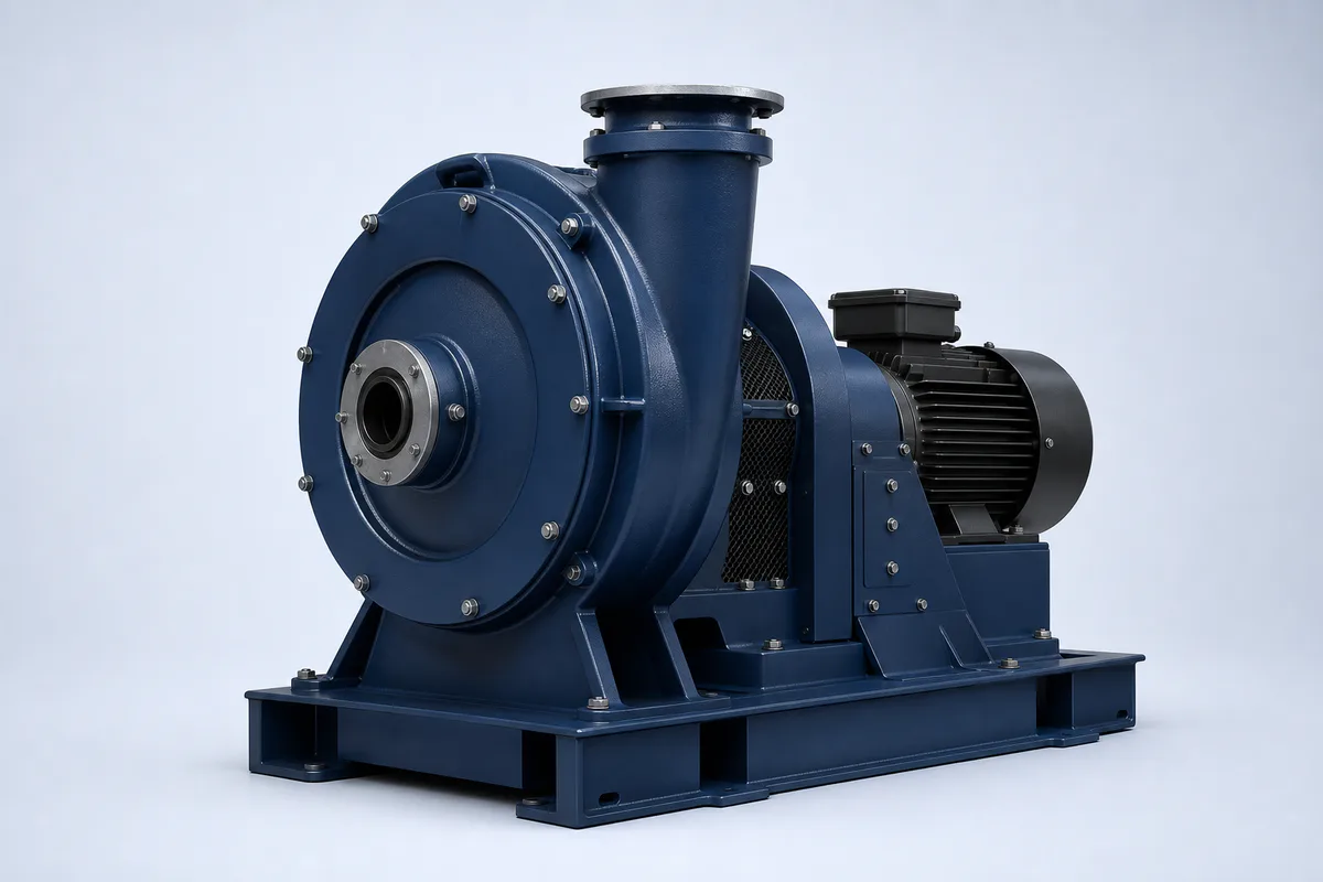
DC-HHF Series · 3rd-generation energy-saving product
High-pressure fan
Built for high-resistance duty. Covers 10–20 kW with stable output across 20–65 kPa, suited to high back-pressure ductwork and deep-treatment applications.
Power 10–20 kWPressure range 20–65 kPa3 power ratings5-year warranty24/7 platform monitoring
10–20 kW
Power range
20–65 kPa
Pressure range
5 yr
Warranty
7×24
Remote status & data monitoring
Models and specifications · 3 models
Parameters from the client-supplied airflow datasheet| Model | Power (kW) | Pressure / vacuum range (kPa) | Flow range (m³/min) | Converted flow (m³/h) | Operating points |
|---|---|---|---|---|---|
| DC-HHF10KW | 10 | 20–65 kPa | 8.8–13.6 | 528–816 | 6 sets |
| DC-HHF15KW | 15 | 20–65 kPa | 13.1–20.4 | 786–1224 | 6 sets |
| DC-HHF20KW | 20 | 20–65 kPa | 17.5–27.2 | 1050–1632 | 6 sets |
Full operating parameters
Flow at each Pressure level, in m³/min
| Pressure (kPa) | 10 kW | 15 kW | 20 kW |
|---|---|---|---|
| 65 | 8.8 | 13.1 | 17.5 |
| 60 | 9.3 | 13.9 | 18.6 |
| 50 | 10.4 | 15.5 | 20.7 |
| 40 | 11.4 | 17.2 | 22.9 |
| 30 | 12.5 | 18.8 | 25.0 |
| 20 | 13.6 | 20.4 | 27.2 |
Figures are entered as published in the source datasheet; m³/h values are m³/min × 60. Final selection must be verified against duct resistance, medium and site conditions.
How to read these figures
- · The flow range in the summary takes the minimum and maximum across all operating points
- · The full table keeps every flow figure from the source datasheet
- · Speed, noise, weight and connection dimensions follow the official product manual
Series capability
- · Stable at high pressure
- · Tolerates resistance swings
- · Efficient direct drive
- · IP rating, electrical parameters and connection dimensions: to be added once model documentation is confirmed
Shared Technology Platform
Four series, one 3rd-generation efficiency platform
PM direct drive + Smart VFD + Aerodynamic optimisation + Data O&M — Full technical explanation on the Technology page →
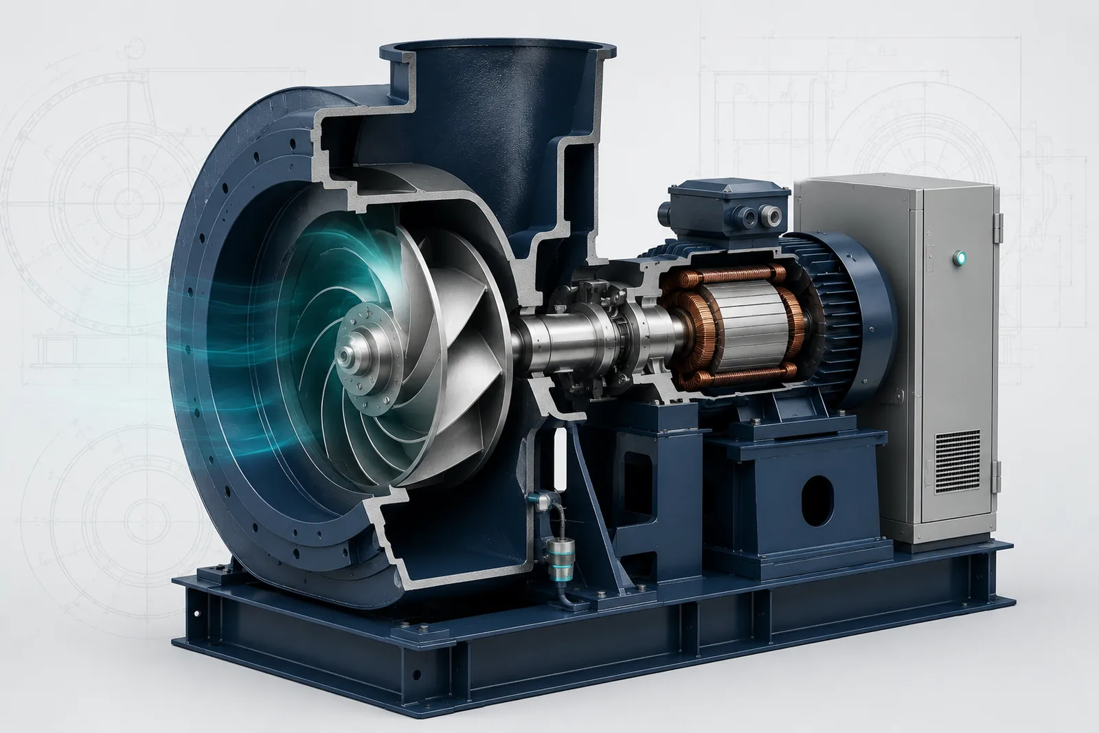
Permanent-magnet motor
No sharp drop-off at part load; less energy under varying conditions
Direct drive
Less transmission loss and fewer wear parts, so less maintenance and downtime
Smart VFD · demand-based airflow
A small drop in speed can mean a much larger drop in power
3D-flow impeller + tapered volute
More useful output under the same conditions
01
Site parameters
Confirm flow, pressure, medium, space and electrical conditions
02
Model recommendation
Selection and savings assessment issued against your conditions
03
Installation
In-situ replacement or parallel changeover within a shutdown window
04
Commissioning
Performance measured on site, acceptance documents handed over
05
Platform onboarding
Connected to the smart O&M platform, data tracking begins
Applications
FAQ
About DC-HHF Series
How much could a High-pressure fan save at your site?
Leave your basic details and we'll produce a preliminary savings estimate before deciding on a survey and quotation.